
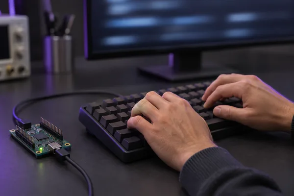
Why a hardware abstraction layer exists
2 min readA product that starts on a Raspberry Pi prototype often ships on a custom carrier board with a different SoC, a different pin-out and different sensors. If your application code is full of board-specific details, a board change means rewriting the code. A a software layer that defines a stable interface for hardware operations so higher code never touches hardware directly, or HAL, stops that. It gives the application a small vocabulary of operations such as read_sensor and set_output, and every board supplies a backend that implements them.
A HAL earns its keep in three ways. First, portability: the same application logic runs on any board that provides a backend. Second, testability: you can build the application on a fast host with a a stand-in object that implements an interface with canned or recorded behaviour, used in place of real hardware in tests backend, so the whole logic is exercised without touching a board. Third, parallel development: one person writes the application against the interface while another brings up the real backend, because the interface was agreed first. That third point is the discipline behind the whole lesson: interface-first design. Write the interface before you write either implementation, and every decision after that becomes replaceable.
The cost of a HAL is indirection: one more layer, one more function call, sometimes a virtual call. On an embedded target that cost is almost always invisible next to the actual I/O, and later sections measure it rather than guess. The alternative, a product where the logic and the board details are one entangled blob, is what you inherit when a prototype is hurried into production, and it is the single biggest reason an embedded codebase cannot be tested on a host.
A GPIO miswired to 5 V can destroy a 3.3 V board. Prototype the logic against a mock first, and only attach real electronics once the software is known good and the voltage levels are checked.
The Linux device model from user space
2 min readBefore you can abstract hardware you must see it the way Linux exposes it. Linux turns hardware into files, in two different flavours. A a special file in /dev that represents a device; the kernel routes I/O on it to a driver identified by major and minor numbers is a file you can open, read and write, such as /dev/i2c-1 or /dev/input/event0. Each node carries a major number that selects a driver and a minor number that selects an instance, visible in the ls -l listing as two numbers before the date. The same idea appears everywhere: /dev/ttyAMA0 has major 204 and minor 64, and /dev/ttyAMA1 has the same major with minor 65 because one driver serves all four UARTs.
Devices split into three kinds. A a device accessed as an unbuffered byte stream through a node, the usual choice for custom hardware does unbuffered read and write, which is why device code avoids stdio buffering and calls open, read and write directly. Block devices add a heavy buffering layer for mass storage. Network devices have no node at all; you reach them through sockets. The important one here is the character device, because GPIO, I2C, SPI and input all appear as character devices or files under sysfs.
The other flavour is a virtual filesystem mounted at /sys that exposes kernel objects, device attributes and their relationships as files and directories. Where /dev gives you a stream, /sys gives you named attributes to read and write, one value per file. /sys/class groups devices by function (tty, gpio, leds, pwm), /sys/bus groups them by bus (i2c, spi, usb), and /sys/devices shows the physical topology. A single device therefore has two faces: an openable node in /dev and a set of attributes in /sys, and udev uses the latter to create and configure the former.
The escape hatch that ties them together is the ioctl system call, ioctl(fd, request, arg), which sends a driver-specific command and pointer to a device. When read and write are too thin, ioctl carries a structured command, which is exactly how I2C and SPI transactions reach user space. The rest of this lesson walks each interface: GPIO, I2C, SPI, PWM, LEDs, input events, then how you discover the right node and lock all of it behind a HAL.
GPIO from user space: libgpiod and the character device
4 min readgeneral-purpose input/output: an individual digital pin that you can configure as an input or an output and read or drive high or low is the simplest hardware interface, used for LEDs, buttons, relays and simple sensors. There are two ways to reach GPIO from user space, and only one of them is current.
The legacy interface is sysfs. Writing a global GPIO number to /sys/class/gpio/export creates a /sys/class/gpio/gpioN directory, whose direction, value, edge and active_low files you then read and write. It works, but it is deprecated since kernel 4.8 (2016), and it has structural flaws: lines are identified by a global number that varies between boards, a line must be exported and unexported by hand and stays exported if a process dies, and there is no way to claim several lines atomically. The current interface is the character device /dev/gpiochipN, one node per GPIO controller, where you request lines by a stable offset within that chip.
The tool and library for that interface is libgpiod, a userspace library and command suite (gpiodetect, gpioinfo, gpioset, gpioget, gpiomon) for the GPIO character device. The tools are the fastest way to confirm a pin works:
gpiodetect              # one chip per GPIO controller, with label and line count
gpioinfo gpiochip0      # per line: offset, name, consumer, direction, flags
gpioset gpiochip0 4=1   # drive line 4 high; held until the command ends
gpioget gpiochip0 17    # read line 17
gpiomon gpiochip0 17    # print timestamped events as line 17 changes
gpiofind led0           # find which chip and offset carry a named line
gpiodetect prints one line per chip, for example a chip labelled pinctrl-bcm2835 with its line count; the exact names and counts depend on your board. gpioinfo shows, for each line, its offset, an optional device-tree name, the consumer that holds it if any, and its direction. These two are your first move whenever a pin seems dead, because they tell you which chip and offset a pin actually is, which is rarely the number printed on the silkscreen.
The C API follows the same model. libgpiod 2.0 (2022) changed the object model to request handles, but the widely documented 1.x names below remain the easiest to read; the tools are identical in both versions:
#include <gpiod.h>
#include <unistd.h>

int main(void)
{
    struct gpiod_chip *chip = gpiod_chip_open("/dev/gpiochip0");
    struct gpiod_line *led  = gpiod_chip_get_line(chip, 4);
    struct gpiod_line *btn  = gpiod_chip_get_line(chip, 17);

    gpiod_line_request_output(led, "led-demo", 0);
    gpiod_line_request_input(btn, "led-demo");

    for (int i = 0; i < 5; i++) {
        gpiod_line_set_value(led, 1);
        usleep(500000);
        gpiod_line_set_value(led, 0);
        usleep(500000);
    }
    gpiod_line_release(led);
    gpiod_line_release(btn);
    gpiod_chip_close(chip);
    return 0;
}
Build it with gcc blink.c -o blink -lgpiod. The pattern is the lifecycle every backend must respect: open a chip, request lines with a consumer name, use them, release them, close the chip. The consumer string matters, because gpioinfo reports it, and that is how you prove a line belongs to your process rather than to another service.
Open the chip: gpiod_chip_open gives a handle to one /dev/gpiochipN controller
Select lines: gpiod_chip_get_line names a line by offset within that chip
Request: gpiod_line_request_output or _input claims the line for a consumer
Use: set or get the value, or wait for edge events
Release: gpiod_line_release returns the line to the pool
Close: gpiod_chip_close frees the controller handle
Going deeperWhy the sysfs GPIO interface was retired
The sysfs interface could not be fixed because its model was wrong at the root. A global GPIO number is an unstable identifier: the same physical pin is a different number on a different board, and even on one board the mapping depends on probe order. Export and unexport are not reference-counted, so two programs can race over the same line, and a crashed process leaves a line exported forever. Most seriously, each direction or value write is a separate file write, so setting several lines together cannot be atomic; a program that needs two pins to change in the same instant simply cannot express that. The character device fixes all three: lines are addressed by chip and offset, requests are kernel objects that are released automatically when their file descriptor closes, and one ioctl can request a bulk of lines atomically.
I2C from user space: i2c-tools and the ioctl interface
4 min readinter-integrated circuit: a two-wire (SDA and SCL), master-slave serial bus where each slave has a 7-bit address, common for sensors and EEPROMs is the workhorse for reading small peripherals. Of the 128 possible 7-bit addresses, 16 are reserved, leaving 112 usable. Most slaves expose a register map: the first byte of a transaction names a register, and the rest carry data. SMBus, the system management bus, is a protocol subset of I2C used for temperature and voltage sensors on PCs, and it is what many tools use by default.
Each I2C controller appears as a character device, /dev/i2c-N, with major number 89. The i2c-tools package gives you command-line access:
i2cdetect -l                     # list adapters and their device nodes
i2cdetect -y 1                   # probe bus 1 and print the address map
i2cget -y 1 0x50 0x00            # read one register byte from slave 0x50
i2cset -y 1 0x50 0x00 0xAB       # write 0xAB to that register
i2ctransfer -y 1 w1@0x50 0x00 r4@0x50   # write reg addr, then read 4 bytes
i2cdetect -y 1 prints a grid of the 128 addresses, marking which ones answer. It works by issuing quick transactions, which some devices misinterpret, so treat a probe of a live bus as potentially disruptive; the manual pages say the same. i2cget and i2cset use the SMBus single-register style. i2ctransfer is the powerful one: it sends a list of raw I2C messages, which is exactly what your C code does through ioctl.
In C, the simplest form sets the slave address and then uses read and write:
#include <fcntl.h>
#include <unistd.h>
#include <sys/ioctl.h>
#include <linux/i2c-dev.h>
int main(void)
{
int fd = open("/dev/i2c-1", O_RDWR);
unsigned char reg = 0x00, buf[4] = {0};
ioctl(fd, I2C_SLAVE, 0x50); /* set the 7-bit slave address */
write(fd, ®, 1); /* point at register 0 */
read(fd, buf, 4); /* read the 4 bytes that follow */
close(fd);
return 0;
}
The subtlety is between the two transactions. The write ends with a STOP condition, then the read starts a fresh transaction. Many sensors are happy with that, but some require the register address to be followed immediately by a read in the same transaction, which means a repeated START instead of a STOP. The I2C_RDWR ioctl expresses that by passing a list of messages:
#include <linux/i2c.h>   /* i2c_msg, i2c_rdwr_ioctl_data, I2C_M_RD */

unsigned char wreg = 0x00, rbuf[4] = {0};
struct i2c_msg msgs[2] = {
    { .addr = 0x50, .flags = 0,        .len = 1, .buf = &wreg },
    { .addr = 0x50, .flags = I2C_M_RD, .len = 4, .buf = rbuf },
};
struct i2c_rdwr_ioctl_data data = { .msgs = msgs, .nmsgs = 2 };
ioctl(fd, I2C_RDWR, &data);
The adapter emits START, address with write bit, the register byte, then a repeated START, address with read bit, then reads the data and ends with STOP. I2C_M_RD marks a message as a read; the I2C_M_NOSTART flag would instead chain a message without any new start at all, which some devices need. The SMBus helpers, i2c_smbus_read_byte_data and friends, wrap the common single-register cases behind the I2C_SMBUS ioctl, and i2cget uses exactly those.
Going deeperI2C_SLAVE versus I2C_RDWR, and the repeated start
The two interfaces address different needs. I2C_SLAVE plus read and write is the SMBus-style shortcut: each system call is one transaction, and a STOP separates them. I2C_RDWR is the full I2C interface: it takes a pointer to an array of struct i2c_msg and issues them as one operation, generating a repeated START between messages so a register write and read happen in the same bus transaction. A device whose data sheet says "read: write the register pointer, then issue a repeated start" will fail with the shortcut because the STOP resets its internal pointer. When a sensor returns 0xFF for every value, that is the first thing to suspect, and switching from write-then-read to a two-message I2C_RDWR is the fix.
SPI, PWM, LEDs and backlight from user space
4 min readserial peripheral interface: a four-wire (SCLK, MOSI, MISO and a per-device chip select), full-duplex master-slave bus, typically faster than I2C has no addressing; instead each device has its own chip-select wire. Two parameters, clock polarity and clock phase, combine into four SPI modes that the slave's data sheet specifies. The generic user-space driver is spidev, enabled by CONFIG_SPI_SPIDEV and exposed as /dev/spidevB.C, where B is the bus and C the chip-select line. It is meant for prototyping and devices with no in-kernel driver, not as the permanent driver for a production peripheral.
The two mode bits combine into the four SPI modes:
A transfer uses the SPI_IOC_MESSAGE ioctl with one or more struct spi_ioc_transfer entries:
#include <fcntl.h>
#include <unistd.h>
#include <sys/ioctl.h>
#include <linux/spi/spidev.h>

int main(void)
{
    int fd = open("/dev/spidev0.1", O_RDWR);
    unsigned char tx[2] = {0xAA, 0x55};
    unsigned char rx[2] = {0};
    struct spi_ioc_transfer tr = {
        .tx_buf = (unsigned long)tx,
        .rx_buf = (unsigned long)rx,
        .len = 2,
        .speed_hz = 1000000,
        .bits_per_word = 8,
    };

    ioctl(fd, SPI_IOC_MESSAGE(1), &tr);  /* one transfer, full duplex */
    close(fd);
    return 0;
}
Because SPI is full duplex, every transfer both sends and receives; rx holds whatever the device clocked back while you sent. Mode, speed and word size are set with SPI_IOC_WR_MODE, SPI_IOC_WR_MAX_SPEED_HZ and SPI_IOC_WR_BITS_PER_WORD. The canonical example is spidev_test, a small tool that sends a known pattern and prints what came back; it is the first thing to run when you wire a new SPI device, and it also demonstrates the correct ioctl sequence to copy from.
PWM, LEDs and backlight are controlled through sysfs attributes rather than a byte stream. PWM (pulse-width modulation) drives a pin with a fixed period and a variable on-time, used for motor speed and brightness. Each controller is /sys/class/pwm/pwmchipN; you write a number to its export file to create pwm0, then configure it:
echo 0 > /sys/class/pwm/pwmchip0/export        # create pwm0
echo 20000000 > /sys/class/pwm/pwmchip0/pwm0/period      # 20 ms in ns
echo 1500000  > /sys/class/pwm/pwmchip0/pwm0/duty_cycle  # 1.5 ms in ns
echo 1        > /sys/class/pwm/pwmchip0/pwm0/enable      # start output
period and duty_cycle are in nanoseconds, and polarity can be normal or inversed. The LED class is separate: each LED is a directory under /sys/class/leds, with brightness ranging from 0 to max_brightness, and a trigger file that makes the LED respond to events such as heartbeat, timer or mmc0 instead of manual control. The backlight class, /sys/class/backlight/
A Raspberry Pi GPIO is 3.3 V and not 5 V tolerant. An SPI or I2C sensor on a 5 V board needs a level shifter, and I2C needs pull-up resistors on SDA and SCL. Check the data sheet before wiring, or the first transfer can damage the board.
Input events: the evdev ABI
3 min readButtons, switches and touchscreens do not get their own ad-hoc device nodes; the input subsystem funnels them all into one interface called the Linux input event device interface: character devices in /dev/input/eventN that deliver a stream of struct input_event records. A GPIO button wired through the input subsystem, or a USB keyboard, or a touchscreen all produce the same structure, so one reader handles them all.
The structure is defined in the kernel header linux/input.h:
struct input_event {
    struct timeval time;  /* timestamp */
    __u16 type;           /* EV_KEY, EV_REL, EV_ABS, EV_SYN, ... */
    __u16 code;           /* which button or axis */
    __s32 value;          /* its new state or magnitude */
};
The three semantic fields do the work. type selects the family: EV_KEY for buttons and keys, EV_REL for relative axes such as a mouse, EV_ABS for absolute axes such as a touchscreen, and EV_SYN as a synchronisation delimiter. Within a type, code names the specific control, for example BTN_0 for a GPIO button or KEY_POWER for a power key. value carries the state: for EV_KEY it is 0 for released, 1 for pressed, 2 for auto-repeat; for an axis it is the position. One physical change produces several records, grouped and ended by an EV_SYN with code SYN_REPORT, and a reader must wait for that delimiter before acting on a group. A button press is therefore two to three records, not one.
The three EV_KEY states form a simple machine:
Reading is a plain loop over fixed-size records:
#include <fcntl.h>
#include <unistd.h>
#include <stdio.h>
#include <linux/input.h>

int main(void)
{
    int fd = open("/dev/input/event0", O_RDONLY);
    struct input_event ev;
    while (read(fd, &ev, sizeof(ev)) == sizeof(ev)) {
        if (ev.type == EV_KEY && ev.code == BTN_0)
            printf("button %s\n", ev.value ? "down" : "up");
    }
    return 0;
}
The record is 24 bytes on 64-bit systems (struct timeval is 16 bytes there) and 16 bytes on 32-bit, so a reader must always use sizeof(ev) and never a hard-coded length. The evtest tool prints events in human-readable form and is the standard way to check a new device; /proc/bus/input/devices lists every input device and which event node it maps to. A key point for a HAL: because evdev is uniform, your button-reading backend can be written once and reused for any button, which is abstraction happening for free at the kernel boundary.
Device discovery and access control with udev
4 min readYour code must find the right node before it can open it, and it must be allowed to open it. Both problems are solved by discovery and by the device manager that listens for kernel uevents and creates, names, sets permissions on and symlinks device nodes according to rules. Node names are not stable: a board with two I2C controllers might number them differently across kernels, and a USB device appears as a different /dev/ttyUSB* each time. Hard-coding a node name is a bug waiting to happen.
Discovery starts in the filesystem. /sys/class groups by function, so /sys/class/i2c-dev lists each adapter and its node name; /sys/bus groups by bus, so /sys/bus/i2c/devices shows what is attached to each bus; /proc/device-tree (mirrored at /sys/firmware/devicetree/base) exposes the device tree itself, so you can read /proc/device-tree/model and the compatible strings to confirm which board you are on. The udevadm info command walks the attributes of a node and shows every property you can match on, and udevadm monitor prints events live as you plug hardware in, which is the fastest way to learn what a device reports.
Access control is where udev earns its keep. By default most device nodes are root-only, and an application that runs as a non-root user simply cannot open them. The fix is a rule file under /etc/udev/rules.d:
# /etc/udev/rules.d/99-sensor.rules
SUBSYSTEM=="i2c-dev", KERNEL=="i2c-1", GROUP="i2c", MODE="0660", SYMLINK+="sensor-bus"
The left-hand keys match (SUBSYSTEM, KERNEL, ATTR, DRIVER, ACTION); the right-hand keys assign (OWNER, GROUP, MODE, NAME, SYMLINK). The operators differ deliberately: == matches, = assigns, += appends, := assigns a final value that later rules cannot override. The rule above takes the I2C adapter that the kernel names i2c-1, gives it group i2c with read-write for owner and group, and creates the stable symlink /dev/sensor-bus, so the application opens /dev/sensor-bus and never has to know the real name.
The rule's MODE="0660" sets these permissions:
Watch the event: udevadm monitor shows the uevent when the device appears, including its SUBSYSTEM and KERNEL names
Inspect attributes: udevadm info -a -n /dev/i2c-1 lists every property a rule may match on
Write the rule: a file in /etc/udev/rules.d matches the device and assigns GROUP, MODE and a SYMLINK
Reload: udevadm control --reload-rules makes udevd read the new file
Reapply: udevadm trigger --subsystem-match=i2c-dev replays events so the rule runs now
Verify: ls -l /dev/sensor-bus shows the symlink, owner, group and mode you asked for
Common failures here have a symptom, a cause and a fix. The symlink does not appear: the rule matched nothing, usually because KERNEL names the wrong number; diagnose with udevadm info, fix the match key. The node exists but the app still gets permission denied: you forgot to reload and trigger, or the user is not in the group; reload, trigger, and check id of the user. The mode gets overwritten: a later rule reassigned it, so use := for the final value or renumber your file to run last.
Designing the HAL: interfaces, backends and injection
3 min readThe earlier sections showed the raw hardware interfaces. Now the discipline begins: none of that detail may appear in your application logic. Start from the interface. A HAL for a button and an LED needs only two operations plus a way to clean up:
/* hal.h — the interface every backend must satisfy */
typedef struct {
    void (*set_led)(int on);     /* drive the LED */
    int  (*read_button)(void);   /* 1 if pressed, 0 otherwise */
    void (*close)(void);         /* release the hardware */
} hal_ops;

/* application code only ever sees this pointer */
void run_product(const hal_ops *hal);
The real backend fills those function pointers with libgpiod calls; the mock fills them with an in-memory variable. run_product is then completely portable: it compiles and runs on the host, on a different board, and in CI, unchanged, because it never mentions GPIO, a chip offset or a device node. That single header is the interface-first design the whole lesson is about, and it is where most embedded codebases fail, because the temptation is to call gpiod_line_set_value directly from inside the business logic.
Two design questions follow. First, how is the backend chosen? Link-time selection picks one backend at build time: two source files implement the same interface, and the build system compiles only one. It is simple and has zero runtime cost, at the price of needing a rebuild to switch. Runtime selection loads the backend at start-up, chosen by a command-line flag, an environment variable or a config file; it lets one binary serve every board, at the price of one more indirection. Second, how does the chosen backend reach the code that uses it? That is a design where an object receives its dependencies from outside, instead of creating or locating them itself. Constructor injection passes the backend when an object is created; setter injection assigns it afterwards; a registry, or service locator, holds the current backend behind a name. The one pattern to avoid is the global singleton, because a global variable holding the one true hardware object can never be swapped for a mock, which quietly kills testability.
Going deeperLink-time versus runtime selection under the hood
Link-time selection is usually just two files and a variable: hal_real.c and hal_mock.c both define the same symbols, and the Makefile or CMake target lists one of them. The linker resolves the call against whichever was compiled in, with zero overhead because the call is a direct branch. Runtime selection needs a form of indirection: a factory function reads the choice and returns one of several statically linked backends, or dlopen loads a shared library whose symbols are looked up with dlsym at start-up. The first keeps everything in one binary and is easy on a read-only root filesystem; the second lets a new board ship as a drop-in .so without re-linking, which matters when the firmware image is fixed and the hardware is not.
A function that calls get_hal() to fetch a global is untestable by construction. A function that receives const hal_ops * as an argument is testable with one line of mock setup. Prefer constructor injection as the default; reach for a registry only when many objects must share one backend.
Mocking hardware and the test strategy
4 min readA mock backend implements the same hal_ops but holds its state in memory instead of touching a pin. For the button and LED interface, a mock is a few lines: set_led stores the last value, read_button returns a value the test sets beforehand, close does nothing. A file-backed variant reads its button state and records its LED state in a file, so a test script can drive it from outside the process. The point is that the mock satisfies the identical interface, so the application code cannot tell the difference, which is exactly what makes the test meaningful.
Testing an embedded application then splits into layers, each run in a different place. Unit tests use mocks and run on the build host in seconds: they verify that run_product calls set_led when read_button reports a press, that it sequences operations correctly, and that it handles error returns. For C++ code, GoogleTest plus GMock generate the mock automatically from the interface and let a test assert that set_led was called with a specific value; the C equivalent is a hand-written mock recording calls into an array. Integration tests bring a few real pieces together, often with a small amount of hardware or an emulator. Hardware-in-the-loop tests, or HIL, run on the real board with real wiring, and they catch everything the mock could not model: an inverted active-low pin, a wrong chip offset, a bus that needs a repeated start, a pull-up resistor that is missing.
The layers run in this order: unit tests on the host against mocks, on every commit, in seconds; integration tests with a few real pieces or an emulated device where a mock is not faithful enough; a cross-compiled build with the real backend, exactly as the previous lesson showed; HIL tests on the board with real wiring, on the bench and in CI when a board is attached; and finally field logs and crash reports from shipped units, which close the loop the lab could not cover.
The trap is imbalance. Teams that only unit-test ship code that fails the first time it meets real hardware, because the mock silently hid the fact that the button is active-low. Teams that only test on hardware cannot afford enough iterations, and their CI is slow and flaky. The pyramid shape is the rule: many fast unit tests at the bottom, a handful of HIL tests at the top. The HAL is what makes the bottom layer possible at all, which is why abstraction and testability are one topic rather than two.
Common mistakes when abstracting and testing hardware. The button reads high when idle: the pin is active-low, and the mock hid it because the mock agreed with the code's assumption; diagnose with gpioinfo and gpioset on the real line, fix by modelling active-low in the interface and the mock. A sensor returns 0xFF on the board but worked in the mock: the mock never enforced the repeated start; diagnose by re-reading the data sheet and switching to I2C_RDWR. Tests pass on the host and fail only in CI on hardware: the HIL test depends on a pin number that differs between the two boards; fix by naming lines in the device tree and looking them up with gpiofind, never by hard-coded offsets. The real backend leaks a line: a code path returned without calling release; diagnose with gpioinfo showing your consumer still holding the line, and fix with cleanup on every path, which RAII gives you for free in C++.
Advanced I/O: line events, IIO, serial and the cost of abstraction
4 min readGPIO line events. Reading a button by polling its value in a loop burns a full core and can still miss a fast pulse. libgpiod instead lets you wait for an edge: request the line for rising or falling edges, then block in gpiod_line_event_wait (which uses poll on the line's file descriptor), and read a timestamped event when it arrives. The gpiomon tool is the same mechanism from the shell. Bulk line operations take the idea further for outputs: gpiod_line_request_bulk_output claims several lines in one atomic request, and gpiod_line_set_value_bulk sets them all in one call, so a bank of relays changes together instead of one at a time.
IIO for sampled sensors. industrial I/O: the kernel subsystem for sensors that produce sampled values, such as ADCs, accelerometers and gyroscopes, exposed under /sys/bus/iio handles the case where a sensor produces a stream of measurements rather than a single register. Each device is /sys/bus/iio/devices/iio:deviceN, with attributes named by channel, such as in_voltage0_raw for the raw ADC value and in_voltage_scale to convert it to volts. Triggers decide when a sample is taken, and buffers gather samples for bulk read, enabled through /sys/bus/iio/devices/iio:device0/buffer/enable and read from /dev/iio:device0. The libiio tools iio_info and iio_readdev browse and stream these, and the libiio library gives C code channels, triggers and buffers without parsing sysfs by hand.
Serial from user space. A UART is a character device such as /dev/ttyS0, /dev/ttyAMA0 or /dev/ttyUSB0, configured with termios. The two modes are the key point: canonical mode buffers a whole line and processes backspace and the return key, while raw mode passes every byte through immediately, which is what most device protocols want. The switch is cfmakeraw plus a few flags:
#include <termios.h>
#include <unistd.h>

struct termios tio;
tcgetattr(fd, &tio);
cfmakeraw(&tio);                    /* raw: no echo, no line discipline */
tio.c_cflag |= CLOCAL | CREAD;      /* ignore modem lines, enable receiver */
cfsetispeed(&tio, B115200);
cfsetospeed(&tio, B115200);
tcsetattr(fd, TCSANOW, &tio);
Parity, stop bits and hardware flow control are c_cflag bits: PARENB and PARODD select parity, CSTOPB selects two stop bits, CRTSCTS enables RTS/CTS flow control. baud rates are the B* constants. Reading raw data blocks until VMIN bytes or VTIME tenths-of-a-second elapse, so a protocol parser sets those deliberately rather than assuming one read equals one packet.
The cost of abstraction. The honest question is what the extra layer costs. A C function pointer costs an indirect branch; a C++ virtual call costs the same plus a vtable lookup, and it stops the compiler from inlining the call. In C++, templates and concepts, and in Rust, generics and traits, provide zero-cost abstraction by resolving the call at compile time. But in this domain the abstraction sits above a syscall: a gpiod_line_set_value ultimately costs a kernel round trip measured in microseconds, against which one indirect branch is noise. The rule is practical, not dogmatic: keep the HAL interface clean and let it be virtual or indirect; optimise only where profiling shows the call itself, not the I/O, is the cost. A HAL that is hard to test to save a nanosecond is a bad trade.
Going deeperWhat a virtual call actually costs, and when it does not matter
A virtual call loads the object's vtable pointer, then loads the function pointer at a fixed offset and branches through it. That is one extra load and one indirect branch, and because the branch target depends on data the CPU cannot predict it as well as a direct call; on top of that, the compiler cannot inline the body. The total is a handful of cycles on a modern core. It only becomes measurable when the call is in a very hot loop and does very little, which a hardware call never does, since a syscall costs thousands of cycles by comparison. Where the loop is pure logic and truly hot, the C++ answer is a template taking the backend as a type parameter, and the Rust answer is a generic over a trait, both of which erase the indirection at compile time while keeping the interface.
Try it
1 min readOpen the lab for this lesson. Install libgpiod and i2c-tools, use gpiodetect and gpioinfo to find an LED and a button, and drive them with gpioset and gpioget before writing the C equivalent. Define the hal_ops interface, implement a real backend with libgpiod and a mock backend that records its calls, then write a unit test that runs the same application logic against both. Read a sensor register over I2C with i2cget and i2ctransfer, and add a udev rule so a dedicated non-root user can reach the node through a stable symlink. The practice pack has the step-by-step tasks and the wiring, and none of the answers are in this lesson.
Key takeaways
- A HAL isolates business logic from hardware specifics, so the same code runs on different boards and under test on a host.
- Linux exposes hardware as files: device nodes for byte-stream devices and sysfs attributes for simple knobs.
- libgpiod and the /dev/gpiochipN character device replace the deprecated sysfs GPIO interface.
- I2C and SPI reach user space through ioctl on /dev/i2c-N and /dev/spidev; sysfs handles PWM, LEDs and backlight.
- evdev turns buttons and axes into a uniform struct input_event stream on /dev/input/eventN.
- udev rules turn a device node into the right name, owner, group and symlink for a non-root application.
- Dependency injection and mocks let unit tests run on a build host with no hardware, in seconds.
- Unit tests catch logic bugs; hardware-in-the-loop tests catch everything the mock could not model.
Reflect
- Explain to a colleague, in two sentences: explain why a hardware abstraction layer makes an application portable and testable without hardware
- Which objective are you least sure about? Re-read that section, then do its exercise in the practice pack.
- What surprised you when you ran the commands yourself?
On a real board
Repeat the key commands on your Raspberry Pi or lab board over SSH or the serial console. Note anything that behaves differently from your PC, such as missing tools, a BusyBox shell or a read-only filesystem.
References and further reading
- Official docsGPIO character device userspace API (kernel documentation)
- Official docsImplementing I2C device drivers: the dev-interface (kernel documentation)
- Official docsSPI userspace API: spidev (kernel documentation)
- Official docsLinux input subsystem: evdev (kernel documentation)
- Man pageudev and udevadm manual pages
- Man pagetermios(3)
- Official docsIndustrial I/O subsystem (kernel documentation)
Official documentation first. Links checked when the lesson was published.